The manual antenna tuner is a device used to match the impedance of an antenna to a transmitter or receiver,
improving signal quality and reducing losses, using a simple and effective design.
Definition and Purpose
A manual antenna tuner is an electronic device that is used to match the impedance of an antenna to a transmitter or receiver, ensuring maximum power transfer and minimal signal loss. The purpose of a manual antenna tuner is to improve the efficiency of the antenna system, allowing for better signal quality and reduced interference. This is achieved by adjusting the tuner’s components to resonate at the correct frequency, thereby matching the impedance of the antenna to the transmitter or receiver. The manual antenna tuner is typically used in amateur radio and other applications where antenna impedance matching is critical. By using a manual antenna tuner, users can optimize their antenna system’s performance, reducing signal loss and improving overall communication quality. The device is usually composed of a variable capacitor and an inductor, which are adjusted to achieve the optimal impedance match. Proper use of a manual antenna tuner requires an understanding of antenna theory and impedance matching principles.
Importance of Manual Antenna Tuner
The manual antenna tuner plays a crucial role in ensuring the efficient operation of an antenna system, and its importance cannot be overstated. By providing a means to match the impedance of the antenna to the transmitter or receiver, the manual antenna tuner helps to minimize signal loss and maximize power transfer. This is particularly important in applications where signal quality is critical, such as in amateur radio and emergency communication systems. The use of a manual antenna tuner can also help to reduce interference and improve the overall reliability of the antenna system. Furthermore, a manual antenna tuner can help to prolong the life of the transmitter and receiver by reducing the risk of damage caused by mismatched impedance. Overall, the manual antenna tuner is a vital component in many antenna systems, and its importance should not be overlooked. It is a simple yet effective device that can make a significant difference in the performance of an antenna system. Proper tuning is essential to achieve optimal results.
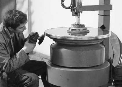
Components of Manual Antenna Tuner
Manual antenna tuners have various
components including capacitors and inductors.
Circuit Diagram
A manual antenna tuner’s circuit diagram typically consists of a network of capacitors and inductors, which are used to match the impedance of the antenna to the transmitter or receiver. The circuit diagram is usually designed to be simple and easy to understand, with clear labels and markings to indicate the different components and their connections. The diagram will typically show the input and output connectors, as well as the tuning controls, which are used to adjust the capacitance and inductance of the circuit to achieve the desired impedance match. By studying the circuit diagram, it is possible to gain a clear understanding of how the manual antenna tuner works and how it can be used to improve the performance of an antenna system. The circuit diagram is an essential tool for anyone looking to build or repair a manual antenna tuner, and it is often provided in the manufacturer’s instructions or online documentation.
Variable Capacitor
The variable capacitor is a crucial component in a manual antenna tuner, allowing for the adjustment of capacitance to achieve the desired impedance match. This component is typically an air-spaced capacitor, which provides a high degree of stability and reliability. The variable capacitor is usually designed to have a wide range of capacitance values, allowing for precise tuning and matching of the antenna’s impedance. In a manual antenna tuner, the variable capacitor is often used in conjunction with an inductor to form an LC circuit, which provides the necessary impedance matching. The variable capacitor is typically mounted on a shaft or dial, allowing for easy adjustment and tuning. By adjusting the variable capacitor, the user can optimize the performance of the antenna system, ensuring maximum signal strength and minimal losses. The variable capacitor is a key component in the manual antenna tuner, and its quality and performance can significantly impact the overall effectiveness of the device.
Building a Manual Antenna Tuner
Constructing a manual antenna tuner requires basic electronics knowledge and skills, using components like capacitors and inductors to create a functional device easily.
Tools and Materials Needed
To build a manual antenna tuner, several tools and materials are required, including a soldering iron, solder, wire cutters, and a multimeter.
A variable capacitor is also necessary, with a range of 500 pF or more, as well as an inductor, preferably with a high Q factor.
A chassis or enclosure is needed to house the components, and a coaxial cable is required for connection to the antenna and transmitter.
Other materials, such as a tuning knob, a meter, and a switch, may also be necessary, depending on the design of the tuner.
A list of the required components and tools should be compiled before starting the project, to ensure that everything is available and to avoid delays.
The quality of the materials used can affect the performance of the tuner, so it is essential to choose components that are suitable for the task.
With the right tools and materials, building a manual antenna tuner can be a rewarding and educational project.
Assembly and Testing
The assembly of the manual antenna tuner involves connecting the components according to the circuit diagram, using a soldering iron and solder to make the connections.
It is essential to double-check the connections to ensure that they are correct and to avoid any mistakes.
Once the assembly is complete, the tuner should be tested to ensure that it is working correctly, using a multimeter to measure the impedance and a signal generator to test the tuning range.
The tuner should be able to match the impedance of the antenna to the transmitter, and the standing wave ratio (SWR) should be minimal.
If any problems are encountered during testing, the tuner should be disassembled and the connections checked again, to identify and correct any errors.
With careful assembly and testing, a manual antenna tuner can be built that provides reliable and efficient operation, and improves the performance of the antenna system.
The testing process may require some trial and error, but the end result will be a well-functioning manual antenna tuner.
Operating the Manual Antenna Tuner
Manual antenna tuner operation involves adjusting settings for optimal signal quality and minimal loss, using a simple and effective process.
Adjusting the Capacitor
Adjusting the capacitor is a crucial step in operating a manual antenna tuner, as it allows for the matching of the antenna’s impedance to the transmitter or receiver. The variable capacitor is typically adjusted by turning a knob or dial, which changes the capacitance and allows for the optimal matching of the antenna’s impedance. This process is often done in conjunction with monitoring the SWR meter, which provides feedback on the quality of the match. By adjusting the capacitor and monitoring the SWR, the operator can achieve a good match and minimize losses. The capacitor adjustment process typically involves a series of small adjustments, with the operator checking the SWR meter after each adjustment to determine the optimal setting. With practice, the process of adjusting the capacitor becomes second nature, and the operator can quickly and easily achieve a good match. The goal is to achieve a low SWR, which indicates a good match and minimal losses.
Monitoring the SWR
Monitoring the Standing Wave Ratio (SWR) is a critical aspect of operating a manual antenna tuner, as it provides feedback on the quality of the impedance match. The SWR meter is typically connected between the transmitter or receiver and the antenna tuner, and it measures the ratio of the forward and reflected power. A low SWR indicates a good match, while a high SWR indicates a poor match and potential losses. The SWR meter is usually calibrated to display the SWR as a ratio, such as 1:1 or 3:1. By monitoring the SWR, the operator can adjust the capacitor and other components to achieve the optimal match. The goal is to achieve an SWR of 1:1, which indicates a perfect match and minimal losses. The SWR meter is an essential tool for optimizing the performance of the antenna system, and it is used in conjunction with the manual antenna tuner to achieve the best possible results. The SWR meter provides a clear and accurate indication of the impedance match, allowing the operator to make adjustments as needed.